With your camera set to a shutter speed of 1/125 or faster, take a couple pictures of a television screen, and see if the bright band in the picture is in exactly the same position on the TV screen for each picture. Since computer screens use a different refresh rate than the NTSC standard, you must use a television screen instead of your computer. If your camera does not show shutter speed, try to make it show the bright/dark bands by using "sport" or "action" modes or a bright background.
NTSC video is refreshed at about 30 frames per second. Frames are interlaced though, so the refresh rate looks like 60/sec, since I can't tell the odd fields from the even fields. If I use a 1/125 shutter speed, about one half of the screen shows illuminated raster lines like you would expect:
60 fields/sec * 1/125 sec = 1/2 field
The weird part is that, picture after picture with my Sony DCS-S50, the EXACT same part of the field is illuminated and does not roll. If I restart the camera, the photos show the illuminated portion in a different location, that then stays the same again picture after picture. If I took pictures with a film camera, the parts illuminated would NEVER be exactly the same. Even if I tried, I could never take a film picture twice of the exact same part of the television refresh cycle. This can only mean that, despite variations in flash, focus, and exposure, my digital camera makes the calculations and adjustments, then waits for its current internal video frame to finish, before finally taking a picture.
Since one digital camera video frame will never finish at the same time as that of another camera (same NTSC or PAL cycle rate, different time of cycle end), the best twin digital camera sync I could ordinarily reliably obtain would be 1/30 sec (0.033 sec) if the synchronization of the cameras is not known.
If you do the math, you will see that when you try to take a picture with a stereo digital camera rig, there are two possible sync times (time between the two exposures), each with a certain probability that depends on the degree of synchronization (degree of phase difference between the two video cycles) and on exactly when during the video cycle the request for a picture comes. A complete video cycle with the two interlaced frames takes about 1/30 sec or 0.033 sec. Phase sychronization varies from 0 to 360 degrees as the cameras cycle slowly in and out of sync.
| Event | Probability | Sync Time |
| 1 | (360-Phase)/360 | (Phase/360)*0.033 sec |
| 2 | Phase/360 | ((360-Phase)/360)*0.033 sec |
Unless you are a math wiz, the equations may not be easy to visualize, so here is a graph to demonstrate. Time or sync phase are on the horizontal axis, as the sync will slowly change over time since the timing reference crystals in the two cameras are not exactly the same. The vertical axis is the difference in time between each of the twin camera exposures. If you keep track of which camera is which (one master, the other slave), and plot (sync time)=(master-slave), the result is the second graph, which agrees well with experiment (John Hart's twin Nikon digital camera sync data) . The slope direction (positive vs negative) in the second graph depends on which of the two camera crystals is faster.
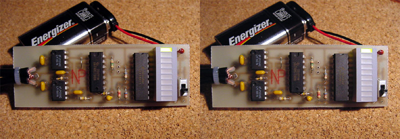
So . . . clearly synchronization of many twin digital cameras can be significantly improved by knowing and allowing for synchronization of the twin cameras' video cycles. You can expect to have a much higher probability that the camera shutters will be sychronized if the camera video cycles are also sychronized. I designed the circuit to show the degree of video cycle signal synchronization.
Heavy filtering with R3 and C5 then converts this pulse width modulation to an analog signal, a voltage that varies from about 0.2 volts to about 4.9 volts, again inversely proportional to the degree of sync. Finally, the LM3914 displays this voltage on a dot scale, with the R5 and R6 divider network setting the top end and ground as the low end of the voltage scale. To keep the comparators of the LM3914 from going off the bottom of the volt scale, the R4 pull-up resistor boosts the bottom voltage by about 0.2 volts to around 0.4 volts.
R7 sets the current through the LED's of the display. With R7 of 620 ohms, the illuminated display LED draws about 20 mA, which is about maximum for this display, probably needed for viewing the display outside. The LED display uses the vast majority of the power for this unit, and a with standard 9v alkaline battery, you can expect about 20 hours of operation. If you plan to use the unit inside in lower light, you could preserve the battery by using double the resistance (1.2K ohms) for R7, for 10 mA through the illuminated LED and about 40 hours battery lifetime.
With the Fairchild Dot display, the top green indicates the lowest voltage and the best sync.


| Part | Value | Digikey Number | Price | Description |
| R1-2 | 680K | 680KEBK-ND | $0.28/5 | 1/8 Watt Carbon Film 5% Resistor |
| R3 | 100K | 100KEBK-ND | $0.28/5 | |
| R4 | 1.0M | 1.0MEBK-ND | $0.028/5 | |
| R5 | 680 ohms | 680EBK-ND | $0.28/5 | |
| R6 | 2.2K | 2.2KEBK-ND | $0.28/5 | |
| R7 | 620 ohms | 620EBK-ND | $0.28/5 | |
| C1-4,C7,C8 | 0.1uF | 399-2127-ND | $0.16 | Ceramic Capacitor 50V 20% |
| C5 | 1uF | P2105-ND | $0.42 | Tantalum Capacitor, 16v |
| C6 | 100uF | P904-ND | $0.42 | Radial Electrolytic Capacitor, 6.3V |
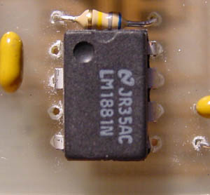
| IC1-2 | LM1881N-ND | $2.78 | Video Sync Separator | |
| IC3 | 296-1603-5-ND | $0.52 | TTL Quad 2-Input NAND Gate | |
| IC4 | LM3914N-1-ND | $2.91 | Dot/Bar Display Driver | |
| IC5 | 160-1066-ND | $2.10 | 10 Element Red Bargraph Dsply | |
| IC6 | 5V | LM2931Z-5.0-ND | $0.86 | 5v 100mA regulator, TO-92, 0.3 volt drop out |
| T1-2 | CP-1403-ND | $0.61 | PCB RCA Jack Horizontal Mount | |
| T3 | Voltmeter Terminal/Wire (optional) | |||
| T4 | 2238K-ND | $0.49 | 9 volt battery clip | |
| S1 | EG1906-ND | $0.71 | PCB Right Angle Switch SPDP |
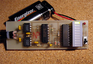
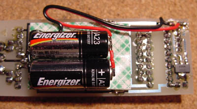 Attach power to the board in the right lower corner. The circuit runs at 5v and the LM3914 needs at least 5.3 volts to regulate at 5v, so you can use the 9v battery clip and 9v battery that will last forever. (The prototype in the pictures used a surface mount voltage regulator instead of the TO-92 specified above). To cut a little weight, you can use a smaller 6v camera battery (Energizer A544 alkaline or L544 lithium), or an even smaller 12v garage door opener battery (Energizer A23)--you can solder directly to the terminals of the battery after sanding the terminals a little, or put a glob of solder on the coiled end of the wires and tape the wire over the ends of the batteries (much easier to change in the field).
If Digikey is out stock of one of the resisitors, use a 1/ 4 watt instead, with part number ___QBK-ND instead of ___EBK-ND. If you want the Bargraph display to be Red-Yellow-Green instead of the all red unit in the parts list above, you can order a Red-Yellow-Green Bar/Dot Display from Mouser Electronics (no minimum order) part number 512-MV5A164 (Fairchild MV5A164) for $1.39.
Attach power to the board in the right lower corner. The circuit runs at 5v and the LM3914 needs at least 5.3 volts to regulate at 5v, so you can use the 9v battery clip and 9v battery that will last forever. (The prototype in the pictures used a surface mount voltage regulator instead of the TO-92 specified above). To cut a little weight, you can use a smaller 6v camera battery (Energizer A544 alkaline or L544 lithium), or an even smaller 12v garage door opener battery (Energizer A23)--you can solder directly to the terminals of the battery after sanding the terminals a little, or put a glob of solder on the coiled end of the wires and tape the wire over the ends of the batteries (much easier to change in the field).
If Digikey is out stock of one of the resisitors, use a 1/ 4 watt instead, with part number ___QBK-ND instead of ___EBK-ND. If you want the Bargraph display to be Red-Yellow-Green instead of the all red unit in the parts list above, you can order a Red-Yellow-Green Bar/Dot Display from Mouser Electronics (no minimum order) part number 512-MV5A164 (Fairchild MV5A164) for $1.39.
For the video input cables, you can pick up a couple of cables from RadioShack similar to those provided with your camera, cut, strip, and solder them on, or use the RCA PCB terminals in the parts list above connected with your original camera cables. My camera uses a standard 3.5mm stereo jack for video with mono audio at the tip, video in the middle, and ground/shield at the base, but you can test yours with a continuity tester. I used a Dremel motortool to route out two slots along the left end of the board, and used a zip-tie to secure the cables to the board for the prototype boards.
If the 10-element display is not enough detail, you can solder a connector or wire to the three pin terminal at T3. The top pin is the signal lead that varies from about 0.35v (best sync) to 4.97v (worst sync), the bottom pin is ground, and the middle pin is +5v if you need to power the meter from the unit's battery. If you follow the voltage, you will see that the LED display is not linear--above about 3.8 volts, the bottom LED stays on, so that the in-sync part of the display is higher resolution. If you have a voltmeter that can display millivolts, you can considerably improve the resolution of your sync observations, to better than 1 part in 1000. RadioShack has a pocket tester, part 22-802, that has millivolt resolution for about $25. Also, you can easily see if the sync is getting better or getting worse-usually the frame rate of each camera is not exactly the same and the sync will very slowly cycle in and out.
Data as HTML.
Data as Excel worksheet.
However, I think most hobbyists are using a local lab or using online services to have the board made to order. For a local lab, one can draw up a computer design using a program such as CadSoft Computer's Eagle Software. For this small project, the Freeware version is more than adequate. To get you started, Manuel Dejonghe sent to me the Eagle Files for his Sync Shepherd Project. "Right click" this link, "Save Target As" to a place on your computer, then "right click" the saved ZIP file and select "Extract All" to uncompress the file set to a folder, then open the files within the Eagle program. The files include a schematic drawing and a circuit board CAD drawing.
Still another way is to design a board using an online service's proprietary software, then have the service manufacture the board based on the board design you create. I have been using ExpressPCB; their software is easy to use, and their circuit board quality is excellent.
Good Luck,
Rob Crockett
Copyright © 2003 - 2011. All rights reserved.